
PoE Video Intercom Commissioning Checklist: Power, Cabling and Calls
Commission a PoE intercom on a short, known-good cable first. Confirm power allocation and Ethernet link, repeat the test over the installed cable, then verify calls and access functions with all intended devices online.
View technical references
A door station that lights up on the bench can still fail at the entrance. A long cable run, an exhausted switch power budget, or an incorrect network assignment can produce similar symptoms. Test power, Ethernet and application behavior in that order so you can identify which layer is failing before replacing hardware.
1. Confirm the PoE requirements. Use the datasheet for the exact door station and indoor monitor variants. Check the supported IEEE PoE type, the switch's per-port limit and its total available power. Count every device powered by the switch, including cameras and access points. Some switches reserve power based on the device's class or configured allocation, so an idle reading alone is a poor basis for sizing the switch. Keep door-lock power in the design separately and follow the equipment manufacturers' wiring instructions.
2. Calculate the switch budget. Suppose six ports each reserve 15.4 W and two others each reserve 30 W. The switch must allocate 152.4 W in total. A 150 W PoE budget cannot cover those allocations even if the measured idle draw is lower. A 180 W budget leaves 27.6 W under the same assumptions. These are example switch-side allocations. Use your switch's actual per-port allocations and confirm the available budget for its installed power supply.
3. Establish a bench baseline, then test the installed channel. Connect the door station directly to a compatible PoE port with a short patch cable. Record the switch port, detected device, allocated power and link state. Move the same unit to the field cable and compare the results. If the problem follows the field cable, test the full path, including patch leads, connectors and patch panels. A wiremap or continuity check alone cannot show whether the channel will carry power reliably under load. Ask the cabling installer to check the appropriate resistance and resistance-unbalance measurements if the fault persists.
4. Separate loss of power from loss of service. If the unit reboots when infrared illumination turns on or a call starts, compare its uptime with time-stamped PoE events and port error counters. If power and link stay up but calls fail, check the device's address, VLAN, routing and the intended call destination. When testing remote app access, compare the result with a local call to the indoor monitor so a remote access problem does not get mistaken for a wiring fault.
5. Verify the whole installation before handover. With all intended devices connected, test a visitor call, two-way audio, video in low light and the configured door release. Verify each answering destination and check for recovery after an agreed maintenance restart. Record the port, cable ID, PoE allocation, device firmware, call destination and pass or fail result. For a quotation or support request, share that record together with the exact door station, monitor and switch models.
Architectural Comparison Matrix
| Symptom | Check first | Useful evidence |
|---|---|---|
| Station never starts | PoE enabled on the port and enough power available | Detected device and allocated watts |
| Works on the bench but fails at the door | Field cabling and intermediate connections | Same station and switch port tested with a short patch cable |
| Restarts during a call or at night | Power events and link errors at the time of the restart | Device uptime and switch logs |
| Powered and online, but calls fail | Network assignment and call destination | Local monitor and remote app test results |
Frequently Asked Technical Questions
Does a switch with enough PoE ports always have enough power?
Check both the per-port capability and the shared switch budget. The sum of the allocations for all connected devices must fit the available budget.
Can I use a passive injector just because its label says 48 V?
Match the injector to the exact device's documented power requirements. Voltage alone does not establish compatibility with IEEE PoE detection, classification or wiring.
Technical references
Featured Hardware for this Architecture
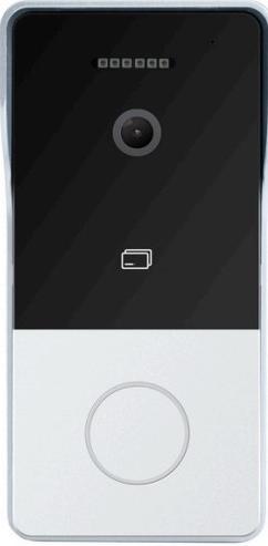
KA-FV5203 - 2K IP Video Door Station
Outdoor call panel with RJ45 Ethernet and IEEE 802.3af PoE support.
KA-FV5203 + KA5703 - PoE Villa Video Intercom Kit
Door station and 7-inch indoor monitor kit for checking visitor calls, video and door release together.
Planning a Commercial or Residential Project?
Contact 1 Karat's solution architects for custom wiring diagrams, sample kit requests, and OEM/ODM manufacturing partnerships.